
Synchronizing time with DCF77 and MSF60
In many of the applications that use the H0420 and Starling programmable audio controllers/players, clock synchronization is a requirement. This is especially the case with the H0420, because it lacks a battery backup for its internal real-time clock —hence, when there is a power drop-out (even for less than a second), the H0420 resets to 1 January 1970 at 00:00 hours.
Even with a backup battery for the real-time clock, when the device is used outdoor, you may observe the clock on the H0420 or Starling to deviate from the true time. The reason is that the crystals used for timekeeping are calibrated for use at room temperature.
The time that the device resets to after power-up, of 1 January 1970 at 00:00 hours, is the "start of the Unix era". This is a commonly used basis for time keeping in operating systems and embedded devices; see the Wikipedia article in the references.
For keeping the time of the H0420/Starling accurate, there are two options: get the time from the network (a typical option for the Starling, as it has a network port), or get the time from some other source, such as a radio signal. This latter option is suitable when no network is available at the location, which is common in outdoor use.
This article specifically discusses how to pick up the current "time of the day" from DCF77 signal, but also discusses MSF60. A particular advantages of synchronizing on a time signal radio station is that "daylight saving time" is automatically handled. When synchronizing the time over the network, it is up to the H0420/Starling controller to correct for the time zone and handle daylight saving time.
Time signal stations & DCF77
There are several time signal radio stations around the world. Unfortunately, these stations use different protocols —which are also incompatible with each other. Since the frequency at which the radio stations transmit also changes, you typically need different receivers modules depending on where you are at the globe. The next table only lists the long wave time servers, by the way. There also exist stations that transmit the time at the short wave. Long wave transmitters have the advantage that the signal more easily bypasses obstacles, such as buildings and mountains.
| Call sign | Description |
|---|---|
| DCF77 | Germany: transmitting from Mainflingen (near Frankfurt) at 77.5 kHz, with a range up to 2000 km |
| HBG | Switzerland: transmitting from Prangins at 75 kHz in a format compatible with DCF77 |
| JJY | Japan: transmitting from Mount Otakadoya (near Fukushima) at 40 kHz and 60 kHz, and from Mount Hagane (located on Kyushu Island) at 60 kHz |
| MSF60 | England: transmitting from Rugby, Warwickshire, at 60 kHz with a range up to 1500 km; from 1 April 2007, the signal will be transmitted from Anthorn |
| RTZ | Russia: transmitting from Irkutsk at 50 kHz |
| TDF | France: transmitting from Allouis (150 km south of Paris) at 162 kHz, in an encoding similar to that of DCF77, but requiring a more complex receiver |
| WWVB | U.S.A.: transmitting from Fort Collins, Colorado, at 60 kHz, received through most of mainland U.S.A. |
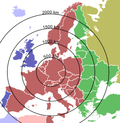
This article focuses on the DCF77 time signal, and it includes notes regarding the MSF60 transmitter further on. The DCF77 time signal can be received in large parts of Europe. The documented reception range is about 1900 km at day and 2100 km at night, under good weather conditions. In general, DCF77 receivers with an internal clock (to bridge periods of no reception or bad reception) operate adequately in a range up to 1500 km.
The reception of the long wave radio signal is easily disturbed by interferences, however. These include atmospheric disturbances and electro-mechanical sources near the antenna of the receiver such as: motors, monitors, power tools, relay racks, etc. The antenna should therefore be positioned with care.
The DCF77 signal transmits the time in local time, which means UTC+1 hour (UTC+2 hours when Daylight Saving Time is in effect; since 1996, Daylight Saving Time is harmonized in Europe). The coloured bands in the map at the right indicate the various time zones in Europe. Great Britain is at UTC-time, Germany is at UTC +1 hour, Greece is at UTC +2 hours (I am ignoring Daylight Saving Time here).
Connecting the receiver module
A suitable, readily built receiver module can be obtained from Conrad and from HKW-Elektronik, see the references at the bottom of this article. Generally speaking, the receiver module needs a single pull-up resistor onto either of its output pins (a 47k resistor would do fine). The H0420 & Starling controllers already have weak pull-ups on its I/O pins, and due to the slow transmission speed, the receiver even works without extra pull-up resistor. On the Conrad receiver, there are two output pins, which are the inverse of each other ("active-low" and "active-high"). Typically, you choose the output that is most convenient. The entire device takes so little current that it can be powered from an I/O pin of the H0420/Starling.
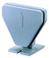
The long wave signal also travels through walls in buildings, but the signal level decreases, of course. It is advised to mount the antenna out-door. Conrad sells a DCF77 receiver in a weather proof enclosure for this purpose. Internally, this product contains the same circuit as the one at the above (i.e. above the one that is pictured at the right).
Connecting the DCF77 receiver to a H0420 is easy, according to the table below and the image for illustration. For best reception, the antenna should be oriented horizontally and perpendicular to the direction to Frankfurt (Mainflingen).
| H0420 pin nr. connector J7 | DCF77 receiver pin nr. | Usage |
|---|---|---|
| 8 | 3 | data |
| 9 | 1 | ground |
| 10 | 2 | power (5V) |
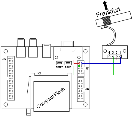 Schematic for connecting the DCF77 receiver to the H0420
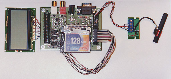
The H0420 with a DCF77 receiver and and LCD to show the time of the day
Decoding time
The receiver module has very little embedded intelligence for decoding the time format: it only detects the variations in the amplitude in the carrier frequency. The receiver gives an "on level" on its output pin when it receives a reduced amplitude and an "off level" for the average amplitude. As said, the "on-level" can be active-high or active-low, depending on which of the two outputs that you are monitoring. For our circuit, a logic "1" would mean an amplitude dip.
The DCF77 radio transmitter reduces the amplitude of the carrier frequency each second (with the exception of the 59th second of each minute) with 6 dB for a duration of 0.1 or 0.2 seconds. These pulses form a stream of bits, 59 in total for each minute. A period of reduced amplitude of 0.1 second should be seen as a logical "0" bit and a 0.2 second period is a "1" bit. The missing pulse on the 59th allows you to synchronize on the start of the data stream for the next minute.
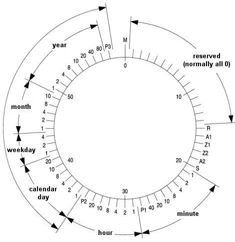
The encoding of the DCF77 signal (one bit each second)
The meaning of the bits is in the above diagram. The first 14 bits must be ignored. The time and date values are in BCD (Binary Coded Decimals) format. The time relates for the minute following that in which it is transmitted. There are three parity bits: one behind the minute, one behind the hour and one behind the date (year); these bits mark "even parity". The meaning of the remaining bits are in the table below.
| Name | Description |
|---|---|
| R | If 1, this time code comes from the reserve antenna |
| A1 | Announcement of "Daylight Saving Time", set from one hour before the status changes |
| Z1 | 1 if daylight saving time is active |
| Z2 | 0 if daylight saving time is active (complement of Z1) |
| A2 | Announcement of a leap second, set from one hour before the status changes |
| S | Start-bit, always 1 |
With this information, the decoding of the DCF77 signal becomes straightforward. You monitor the data pin of the DCF77 receiver and get a timestamp when its value changes. Subtracting the previous timestamp from the current one lets you determine whether the pulse is short or long (0.1 and 0.2 second respectively) and whether the bit should therefore be 0 or 1. The timestamp also lets you detect the minute marker, and if you find it, you can perform some additional checks and get the time & date values from the accumulated bits.
The downloadable archive contains a source file that can be included in your
programs for DCF77 decoding. The module contains two functions: clock_init(power_pin, data_pin)
and clock_decode(pin, status). Function clock_init(power_pin, data_pin)
initializes the module and sets the pin numbers for the power and the data input.
For the connections in this article, these would be 15 and 14 respectively. Your
script must implement the @input(pin, status) function and all events that the
function receives on the DCF77 data pin must be forwarded to clock_decode(),
with the same parameters as those for @input(). You may also just
forward all @input() events to clock_decode(); it returns
immediately for events on any other pin that the one set up with clock_init().
A (minimal) example implementation is below.
@input(pin, status)
    {
    clock_decode(pin, status)
    }
Function clock_decode() returns true after it successfully
received a full date/time stamp, and false for all other calls. If
reception is good, the function will therefore return true at the
start of every new minute. After each good reception, the clock_decode()
adjusts the real-time clock of the controller. You therefore do not need to perform
any additional tasks apart from calling clock_decode() from your
@input() function.
A script that uses the DCF77 module and prints the date and time to an LCD is also included in the archive. This script runs on the H0420.
What the clock_decode() function does in the background is that it
takes a time-stamp on the up and down flanks of the input pin. From that, it
calculates the width of the pulse, and it checks this against the valid pulse
widths of 0.1 and 0.2 seconds and stores a 0 or a 1 bit in an array. The routine
also saves the time stamp of the previous up flank that it saw, and if it sees
that that the previous time-stamp was two seconds ago, it decides that it has
just seen the 59th second gap in the DCF77 protocol. Then, after a
few more checks, clock_decode() updates the real-time clock of the
controller.
Other protocols
The MSF60 protocol uses the same basic principles as DCF77, but the logic for the start of a new minute is different. Instead of a missing 59th second, the MSF60 protocol uses a 0.5 second pulse at the start of a new minute, and in the seconds 53 to 58, an extra wide pulse of 0.3 seconds may appear. Thus, there are four pulse lengths for MSF60:
- 0.1 second, meaning a zero bit (0)
- 0.2 second, meaning a one bit (1), except for seconds 53 to 58, where it means a zero bit (0)
- 0.3 second, meaning a one bit (1) and only valid in the seconds 53 to 58
- 0.5 second, on the start of a new minute
What makes the MSF60 signal slightly more complex is that in the seconds 1 to 17, the MSF60 signal carries the offset of the local time to UTC, but using single and double pulses instead of the narrow and wide pulses described above. Starting with the 17th second, the protocol uses the narrow and wide pulses (0.1 and 0.2 second). In the range of seconds 53 to 58 (inclusive), however, extra wide pulses 0f 0.3 seconds appear. The background for the existence of double pulses and extra wide pulses is that the MSF60 protocol can in fact carry two bits of data per second. To date, the protocol makes very little use of it. See the references of this article for a link to the official specification of the MSF60 time signal.
Some documents describing the MSF60 time code also mention a "fast code" that is transmitted in the first second. This fast code was dropped from service in 1998, however.
If you are interested in local time, you can ignore the first 17 seconds in the timecode. The remaining code is in the table below (the seconds are counted from zero to 59). All BCD values are transmitted "high bit first"; in DCF77, BCD data was transmitted "low bit first". All parity sums should evaluate to odd parity (after taking the parity check bit into account).
| Second | Description |
|---|---|
| 0 | minute marker (0.5 second wide pulse) |
| 1 - 16 | DUT1 code (difference between local time and UTC) |
| 17 - 24 | year in 8-bit BCD |
| 25 - 29 | month in 5-bit BCD |
| 30 - 35 | day of the month in 6-bit BCD |
| 36 - 38 | day of the week in 3-bit BCD |
| 39 - 44 | hour in 6-bit BCD |
| 45 - 51 | minute in 7-bit BCD |
| 52 | always zero |
| 53 | daylight saving time is pending |
| 54 | parity check bit for the year |
| 55 | parity check bit for the combined day plus month |
| 56 | parity check bit for the day of the week |
| 57 | parity check bit for the combined hour plus minute |
| 58 | daylight saving time is in effect |
| 59 | always zero |
Downloads
To get you started, below is an archive file with a complete script and a support file. You can run this script as is, or modify for your purposes.
- A script file that implements a simple DCF77 decoder, that you can put on a CompactFlash card and run.
- A script file that implements a simple MSF60 decoder, that you can put on a CompactFlash card and run.
There are two files in each archive; for the DCF77 example, the main file (the file to compile) is "dcf77.p" and the file "dcf77rx.inc" contains the DCF77 decoding routines which you add to your own scripts without modification. For the MSF60 example, these files are called "msf60.p" and "msf60rx.inc" respectively.
The scripts in the archives assume that the the receiver module is connected to
a H0420 controller as described in this article. If you use a H0440 or choose a
different connection, you need to modify the call to clock_init()
in "dcf77.p" or "msf60p". The script also assumes that an LCD is branched to
connector J6.
Further reading & references
- H0420 Programmable MP3 Player
- The main page for the H0420 MP3 player that this article applies to.
- Starling Programmable Audio Controller
- The main page for the Starling audio player/controller that this article applies to.
- Conrad - international site
- This page allows you to select your country for a localized site. The standard DCF77 receiver module that I used in this article is article number 641138-89. An alternative enclosure, in an IP54 enclosure for out-door mounting, is article number 121177-89; this module may not be available world-wide, however.
- EM2S - Receiver Module MSF 60kHz
- HKW-Elektronik develops and distributes receiver modules for OEM products, notably the well-known EM2S module and the newer EM6 module. These receivers and their matching antennas (for MSF60, WWVB, JJY60 and JJY40) can be ordered from their on-line shop.
- WWVB Receiver modules for OEM development of products
- Galleon distributes the EM2S module (from HKW-Elektronik) for receiving the WWVB time signal in the U.S.A. (Fort Collins, Colorado). This is the same module as needed for MSF60.
- DCF77 -Funkuhr, Decodierung des Zeitsignals
-
An in-depth article on the DCF77 radio signal and the encoding.
In German - Reichweite des DCF77-Senders
-
A page describing experimental receptions of the DCF77 signal, beyond the
documented limit of 2000 km. The original page is in German, but
an English translation
is available on the site as well. The German version contains information as
to why the range is documented as 2000 km, even though the signal is reportedly
received at over twice the distance.
In German -
 MSF Time and Date Code
- The specification for the MSF60 signal by UK's National Physical Laboratory, in PDF format.
- Unix time
- A Wikipedia article on "Unix time", which is the number of seconds since 1 January 1970.
