

Panelizer
A Gerber Panelization tool. At the moment, it supports only panels with a single PCB design that is repeated in a regular grid (of a number of columns and a number of rows). Furthermore, it only supports break-routing.
Downloads and installation
| Microsoft Windows | | Version 0.3 (alpha) |  |
| Linux | | Version 0.3 (alpha) | |
| Source code | | Codeberg project |
The utility is a single small executable. No installation is needed; just unpack and run.
To build the program from source, see the notes at the Codeberg project.
Usage
This is a command line program. It takes options, filenames and response files as parameters on the command line.
Options must start with a dash. Any parameters may be separated from the option with a ‘=’ or with a space. In other words, the options:
-grid 3:5
-grid=3:5
Any parameter that does not start with a dash or an ‘@’, is considered a filename. Gerber files, Excellon drill files and Gerber Job files are supported.
A filename prefixed with an ‘@’ character is a response file. A response file is read and parsed as if the contents of the file was passed on the command line. See below the ‘Option Summary’ topic for more information on response files.
When a Gerber Job file is passed, the program reads (and converts) any file mentioned in the job file.
Option Summary
| Command line option | Description |
|---|---|
-grid colums:rows | The panel lay-out, giving the number of PCBs horizontally and vertically. |
-tab type:offset | Specifies the position of a tab (with perforations, or mouse-bytes). The type must be the letter ‘x’ (for a tab on the horizontal edges) or ‘y’ (for a tab on the vertical edges). The offset is the position of the middle of the tab, relative to the left or bottom edges of the PCB. The offset is in millimetres. The ‘-tab’ command may appear multiple times on the command line. |
-spacing size | The spacing between the PCBs in the panel, as well as between the PCBs and the rails. The size is in millimetres, and the default is 2 mm, both horizontally and vertically. |
‑spacing x‑size:y‑size | The spacing can be separately set for horizontal and vertical spacing (for case when these are not the same). |
-rails size | The width of the rails, in millimetres. The default value is 5 mm (for both horizontal and vertical rails). |
‑rails x‑size:y‑size | If you set two values separated by a colon, it sets the sizes of the rails separately (or omits them if a size is zero). |
-drill size | The diameter of the drill used for the perforation in the tabs (mouse-bytes). The default value is 0.5 mm. |
-tabwidth size | The width of the tabs at their narrowest point (that is, at the centre). The default is 2 mm. |
-tabradius size | The mill radius used for the tabs. The default is 1 mm (for a common 2 mm mill bit). |
-fiducial size | The diameter of the fiducials that are added to the rails. The default is 1 mm. Set this size to zero to omit the fiducials in the rails. |
-tooling size | The diameter of the tooling holes that are added in the rails. The default is 3 mm. Set this size to zero to omit tooling holes. |
-tolerance value | The tolerance for the coordinates of the profile (board outline). The default is 0.001 mm. |
Response files
Options may be written in a response file, and this response file can then be passed to the panelizer program. To do so, prefix the filename of the response file with an ‘@’ character. All options in the file are parsed as if they were passed on the command line.
The options in the response file may be split over multiple lines. Empty lines and comments are ignored. A comment starts with a ‘#’ in the left column and runs to the end of the line.
Names of Gerber and Excellon files may also appear in a response file. However, the files should be mentioned in full; wild-card characters in the filenames are not supported (that is: not supported in a response file, wild-cards are supported on the command line).
Options are parsed in the order that they appear. This also means that when you place a response file before any other options on the command line, the options that follow may overrule the settings in the response file. Inversely, when the response file comes last on the command line, its settings may overrule options before it.
File Requirements
Gerber files must use ‘Leading Zero’ omission; ‘Trailing Zero’ omission has been deprecated since 2014, and this panelizer program no longer supports it.
A Gerber file for the profile (outline, PCB contour) must be provided. This file should contain only the contour; no crop marks and no additional drawings or notes. Other Gerber files should not have the contour included.
The function of a file (‘profile’, copper layer, solder mask, etc.) is established from its contents. The program tries (in this order):
- the file function attribute of the Gerber ‘X2’ format,
- the function declared in the Gerber Job file,
- the name set in the older (and deprecated) ‘LN’ (Layer Name) command, or
- the file extension convention of Protel/Altium (‘.GKO’, ‘.GTL’, etc.).
Our recommendation is to include Gerber X2 attributes in the generated files.
Excellon drill files must be separately provided for plated holes and non-plated holes. Mouse-bytes for the tabs are added as non-plated holes, so a separate file for non-plated drills is needed.
Excellon drill files should use ‘decimal’ format. The ‘leading zero’ and ‘trailing zero’ (LZ & TZ) variants are ambiguous, because the number of digits and decimals are not formally recorded in the drill file. The panelizer program attempts to detect the precision of coordinate values for LZ and TZ modes based on hints, but we recommend to use decimal mode so that there is no ambiguity.
Like for Gerber files, the function of the Excellon files is determined from its contents, or from the declaration in the Gerber Job file; the presence ‘NPTH’ or ‘NonPlated’ in the filename is used as a last resort.
A Gerber Job file is practical, because it lists all Gerber files plus their attributes. However, job files are not widely supported and programs that do support them may leave out Excellon drill files from the job file.
Note that if you add a Gerber Job file on the command line, the panelizer program will create an updated job file for the panel.
Usage Tips
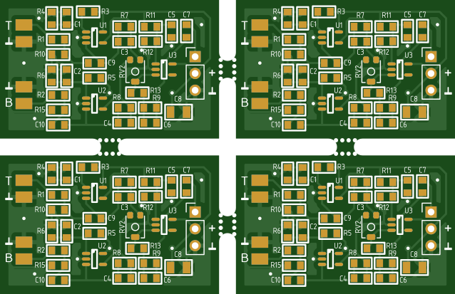
To get from a single PCB design, such as pictured below at the left, to a panel with two columns and two rows, as seen on the right, use the command shown below the pictures.
| Single board | Panel 2x2 with default settings |
|---|---|
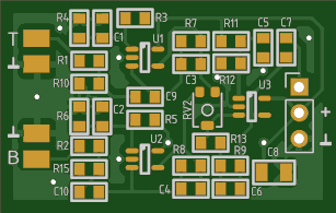 |
 |
panelizer -grid=2:2 preamp-job.gbrjob
This command assumes that you have a Gerber Job file that lists all necessary Gerber and drill files. If not, you can specify the files separately instead, using wild-cards for easy of use:
panelizer -grid=2:2 preamp*.gbr preamp*.drl
You can combine the Gerber Job file with additional files (but make sure no file is mentioned twice). The advantage is that if a job file is given (for the board), the panelizer program creates a new job file for the panel. Any additional files (such as the drill files) are then also included in the panel job file.
No tab settings were given in the previous examples, and so defaults were added. When you run the panelizer program, it will tell you the size of the PCB (as it has detected it) and where it placed any default tabs. You can change the defaults by adding tabs explicitly.
panelizer -grid=2:2 -tab=x:8 -tab=x:18 preamp*.gbr preamp*.drl

Two tabs were added to the horizontal edges of the PCBs, at 8 mm and 18 mm from the left edge of the PCB. More precisely said, the middle of the first tab is 8 mm from the left edge of the PCB. No tabs were explicitly set for the vertical edges, so the defaults are still used for these edges.
In general, we recommend a full frame (rails on all sides) for panels, to add
stiffness and avoid warping during handling or machine placement. It is, however,
configurable. To omit the frame altogether, set the size to zero (the
-rails option).
panelizer -grid=2:2 -rails=0 preamp*.gbr preamp*.drl
To set rails only on top/bottom or on left/right, give two values for the
-rails option, separated by a colon, and where one of these two
values is zero.
panelizer -grid=2:2 -rails=5:0 preamp*.gbr preamp*.drl
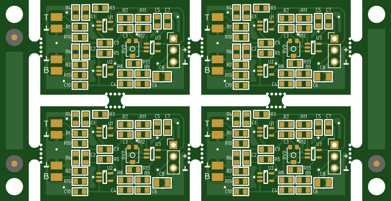
Tooling holes and Fiducials
By default, three fiducials and four tooling holes are added to the rails. The purpose of the fiducials is for automated board handling by pick-&-place machines and others. There are three fiducials, so that the machine can verify the orientation of the panel.
Tooling holes in the rails are useful for registration of a panel on a manual stencil printer. It requires a stencil printer that uses PCB holders with tooling pins, and these pins must match the holes in the panel rails.
If the panel has a full frame (rails on four sides):
- the tooling holes are positioned such that they are centred horizontally and vertically in the rails;
- the fiducials are aligned horizontally to the left and right edges of the first/last PCB in the panel, and vertically they are centred in the rails (and thus aligned with the tooling holes).
When there are only horizontal rails or only vertical rails, the tooling holes are still centred in the rails in one direction, and the margin to the short edge of the rails is set to the same as the margin to the long edges. For example, for a panel with vertical rails only, and assuming that the rails are 5 mm wide, the tooling holes are offset 2.5 mm from the left and right edges of the rails (because the tooling holes are centred in this direction), and they are also placed 2.5 mm from the top or bottom edges of the rails.
Fiducials (in the case of only horizontal or vertical rails) are also centred in the rails in one direction, and are placed relative to the tooling holes at a distance that is equal to the rail width.
The size of both fiducials and tooling holes can be adjusted, and they can be omitted altogether by setting the size to zero.
Errors and Warnings
Note: not all error messages are listed here, because most are self-explanatory.
- WARNING: File function could not be determined, file ‘path’.
-
The panelizer program essentially just repeats a PCB design a number of times
horizontally and vertically, but it does need to make adjustments. For example,
tabs and rails need to be added to the profile data, and extra holes for the
perforation in the tabs need to be added to the drill file for the
‘non-plated’ holes.
So obviously, the program needs to know which of the files holds the profile and which holds the non-plated drill positions. It does this by checking the file contents (or in some cases, the file name). However, if the check fails, it issues this warning.
If the panelizer program cannot find files for the profile and/or the non-plated drills, it will follow up with an error.
- WARNING: Overlapping or collinear line segments in the profile.
-
With ‘collinear line segments’ is meant that an edge of the PCB
may look like a single line segment in the PCB design program (or the Gerber
viewer), but is actually composed of two (or more) segments. These segments
share an endpoint and they have the same slope. Visually, it looks like a
single line segment, technically (as recorded in the Gerber data) it are two
or more segments.
‘Overlapping line segments’ are similar, but now the segments do not ‘connect’ at a shared endpoint; instead, the line segments overlap (partially or fully).
Why this matters, is because the panelizer program has to add tabs to the drawing of the profile, which means that it has to cut holes in some lines and insert the tab drawings into these holes. When a tab is placed at a position where two line segments overlapping or are collinear, it makes the procedure complex. The panelizer program should be able to ‘fix’ cases of overlapping and collinear line segments (which is why this is a warning, and not an error), but it is yet recommended to clean up the PCB outline before feeding it into the panelizer.
- WARNING: Tab radius is reduced to [number] mm, as it is constrained by PCB spacing.
-
The slots between the PCBs are milled with a router bit. This router bit also
determines the radius of the tabs. By convention, PCB fabrication firms use a
2 mm router bit, which implies that the (minimum) PCB spacing is also
2 mm, and that the radius (at the corners and the tabs) is 1 mm
(half of the diameter of the router bit. So the relation between the radius
and the spacing is that the radius must be at most half the spacing
(and if the spacing is different in horizontal and vertical directions, the
smallest of these two).
- ERROR: [Horizontal|Vertical] tab at [number] mm does not fall on an edge.
-
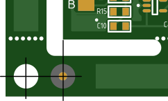
The attachment point of a tabs must be a straight horizontal or vertical line.
The outline of the tab may not exceed the line segment.
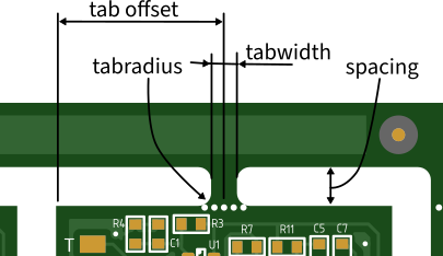
As illustrated in the above picture, the offset that you specify for a tab (with the
-taboption) goes from the left edge or the bottom edge to the middle of the tab. Also, the tab width (that can be set with the-tabwidthoption, and that is 3 mm by default) is the dimension in the middle, where the tab is at its narrowest. At the base (where the tab attaches to the edge), it is wider by the tab radius on both sides.Another cause for this message may be that the edge may not be exactly horizontal or vertical. The current Gerber standard specifies 6 decimals, which (for the case of metric coordinates) corresponds to nanometre precision. With such precision, even the slightest inaccuracy in the floating point computations in the design program may lead to coordinates in the Gerber file that are very close, but not identical. For instance, a line from (100, 50) to (100, 49.999998) is not detected as horizontal.
To mitigate this, the panelizer program snaps all coordinates of the profile to a lower precision. The precision of the CNC machines for milling and routing the PCBs will not exceed 0.01 mm. So in practice, snapping all coordinates to a tolerance of 0.01 mm should be fine. The tolerance can be configured with the
-toleranceoption, the default is 0.001 mm. - ERROR: PCBs are not connected to [horizontal|vertical] rails.
- When there are rails, the PCBs in the panel should have tabs to those rails. Strictly speaking, this error message is therefore self-explanatory. However, this message is often caused by an earlier check whether the tab falls on a horizontal/vertical edge (see the message above). When a tab is found to be at an invalid position, it is removed, and thus it may end up in the situation that there are no more (valid) tabs left.
How it Works
The panelizer program essentially copies the contents of each Gerber and Excellon file multiple times to the output file, while adjusting the X and Y positions of all graphic data. Thus, while it does not use the ‘step & repeat’ command of the Gerber format, it does essentially the same thing.
To this end, the program contains a reduced, conservative Gerber parser: reduced in the sense that it understands only a subset of the Gerber command set, conservative in the sense that it copies everything that is does not understand. This way, the contents in the output file is identical to that of the input file, with the exception that multiple copies of the input appear in the output, and that coordinates are adjusted for all but the first copy.
The Gerber parser follows the current standard (revision 2024.05), but with the exception of a few rarely used (and deprecated) modes. Notably, ‘trailing zero omission’ and ‘incremental coordinates’ are not supported.
Support for the Excellon format follows this same scheme, but the context is more confusing because the Excellon standard is… non-standard. There are four coordinate formats: leading-zero, trailing-zero, decimal or none, but due to the lack of a command to set the precision, only ‘decimal’ mode is fully specified. Regretfully, the other modes are still in common use as well, and properly interpreting the data relies on heuristics to auto-detect the precision. To make processing easier, the panelizer program converts Excellon files to ‘decimal’ mode, if needed. This means that, unlike the case of the Gerber files, the output file may not simply contain multiple copies of the input file.
Acknowledgements
This software uses the ‘Parson’ library by Krzysztof Gabis to parse the Gerber Job file. Parson is distributed under the MIT license.
The images in this documentation were made with the on-line ‘tracespace view’ by Michael Cousins and contributors.
License
Copyright 2026, CompuPhase
Licensed under the Apache License, Version 2.0 (the ‘License’); you may not use this file except in compliance with the License. You may obtain a copy of the License at http://www.apache.org/licenses/LICENSE-2.0
Unless required by applicable law or agreed to in writing, software distributed under the License is distributed on an ‘AS IS’ BASIS, WITHOUT WARRANTIES OR CONDITIONS OF ANY KIND, either express or implied. See the License for the specific language governing permissions limitations under the License.
