

Debouncing switches with vertical counters
Debouncing switch inputs can be done on hardware (with a low-pass filter or a Set/Reset latch), or in software. A well-known software method to debounce multiple switches at once is using vertical counters. Despite being well-known, in literature the method is typically presented as a code dump with little or no explanation. This article presents vertical counters and their use in debouncing in a more comprehensive manner. Knowledge of binary arithmetic and of the C/C++ programming language is required, though.
This article starts with an overview of switch bounces, then goes into the binary arithmetic and logic that is involved with vertical counters. The third section presents an annotated implementation in C, followed by a few refinements. A low latency variant is discussed in that section too.
Understanding switch bounce
When the contacts of mechanical switches toggle from one position to another, these contacts bounce (or "chatter") for a brief moment. This is unavoidable (except with mercury-wetted contacts, but these switches are rare and becoming rarer).
The images below are captured with a Saleae logic analyzer connected directly to a standard pushbutton switch. The first image is of a button press. Clearly visible are the bounces that last for over 4 milliseconds.
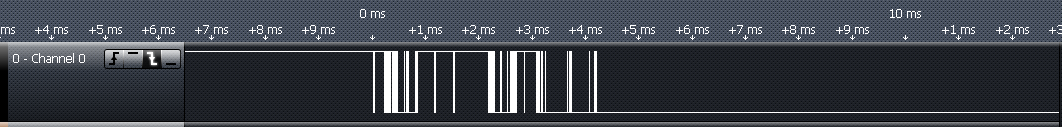
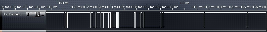
Zooming in on the first millisecond reveals that the bounces are closely spaced and irregular. Although all of it happens in the course of milliseconds, high-speed logic will detect these bounces as genuine presses and releases —unless the bounces are filtered out.
A button release produces bounces too, as the snapshot below demonstrates. It is common for a switch release to produce less bounce than for a switch press, but this is not guaranteed.
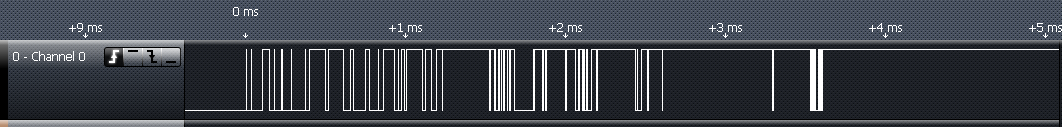
The particular switch used in this test became stable after roughly 5 ms. The time that it takes for a switch to cease bouncing depends on the mechanical construction, as well as how the switch is actuated. Bounce periods exceeding 10 ms have been observed in practice.
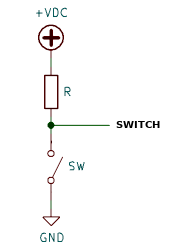
For completeness, the above captures were done with a pushbutton that switches to ground and has a pull-up to the positive voltage, as in the figure below:
Vertical counters
A vertical counter is an array of counters managed in software. The complement would be the “horizontal counter”, and you may imagine a byte as a horizontal counter. Incrementing a byte is handled inside the CPU, we usually view a byte as a value in memory (that ranges between 0 and 255). The trick in understanding vertical counters is to first view the byte as an array of eight individual bits.
Looking at the bits when incrementing a byte seven times, we can observe the logic that the CPU uses to perform the arithmetic. Each row of the table has the most significant bit at the left and the least significant bit at the right.
| b7 | b6 | b5 | b4 | b3 | b2 | b1 | b0 |
|---|---|---|---|---|---|---|---|
| 0 | 0 | 0 | 0 | 0 | 0 | 0 | 0 |
| 0 | 0 | 0 | 0 | 0 | 0 | 0 | 1 |
| 0 | 0 | 0 | 0 | 0 | 0 | 1 | 0 |
| 0 | 0 | 0 | 0 | 0 | 0 | 1 | 1 |
| 0 | 0 | 0 | 0 | 0 | 1 | 0 | 0 |
| 0 | 0 | 0 | 0 | 0 | 1 | 0 | 1 |
| 0 | 0 | 0 | 0 | 0 | 1 | 1 | 0 |
| 0 | 0 | 0 | 0 | 0 | 1 | 1 | 1 |
The least significant bit, or b0, just toggles between 0 and 1. The next bit toggles if b0 is 1, or more specifically: b1,i+1 = b1,i xor b0,i. The next bit, b2, toggles if both b0 and b1 are 1. This scheme is easily extended to more bits.
With vertical counters, the table is rotated by 90°. Each “bit” for the counter is in a separate variable. If you have a three-bit counter, these bits could be in variables cnt0, cnt1 and cnt2, for example. The variables are multiple-bit entities as well —the smallest entity that you can store in micro-controller memory is a byte. With vertical counters, each bit of the variable represents an input.
In other words, with a 32-bit micro-controller, you can debounce up to 32 inputs in parallel, with only a few variables and very efficient arithmetic.
Debouncing in software
What is needed for debouncing is that the inputs stabilize before reporting a switch press or switch release. In hardware, you would build a low-pass filter in front of a logical gate with a Schmitt-trigger input. In software, you take multiple samples of the inputs until the bits have been stable for “long enough”. In practice, you have a periodic timer interrupt that samples the pins, debounces them and reports the debounced outputs.
An annotated implementation
The example implementation debounces up to eight inputs using a 2-bit vertical counter. The function accepts a byte with raw bits read from an I/O port and returns the debounced inputs. The code is trivially adapted to debounce more than 8 inputs at a time.
1 2 3 4 5 6 7 8 9 10 11 12 13 14 15 16 17 18 |
unsigned char debounce(unsigned char sample)
{
    static unsigned char state, cnt0, cnt1;
    unsigned char delta, toggle;

    delta = sample ^ state;

    cnt1 = cnt1 ^ cnt0;
    cnt0 = ~cnt0;

    cnt0 &= delta;
    cnt1 &= delta;

    toggle = cnt0 & cnt1;
    state ^= toggle;

    return state;
} |
- Line 1
- The argument sample holds the raw state of the input pins (the un-debounced state).
- Line 3
- The routine requires three fields with persistent state: two fields to form a 2-bit vertical counter and one field to hold the current (debounced) state of the inputs.
- Line 6
- The variable delta contains a 1 bit for every input that is different from the current debounced state.
- Lines 8 & 9
- These lines update the vertical counter. Line 9 toggles all bits of counter cnt0 (our “vertical bit” 0) and line 8 toggles the bits in cnt1 depending on the old value of cnt0. Since cnt1 depends on the previous value of cnt0, cnt1 is updated before cnt0.
- Lines 11 & 12
-
Any bits in the sample that are the same as that of the current debounced
state are cleared. One consequence is that the vertical counter (in
cnt0 and cnt1)
is only incremented for those bits where the sample is different from the
debounced state. A second consequence is that when there is a “contact
bounce” in the samples where a sample bit momentarily toggles back to
the old state, the vertical counter for that bit is reset to zero.
Note that the operations on lines 11 and 12 can be combined with those on lines 8 and 9, for more compact code.
- Line 14
- Variable toggle gets a 1 bit at every position in which cnt0 and cnt1 have a one bit —that is, when the vertical count (for that bit position) is 3. Since the vertical count is reset on a contact bounce, a vertical count of 3 means that the respective bit has remained stable for 3 consecutive samples. So, variable toggle has a 1 bit for every bit that must be toggled in the output state.
- Line 15
- Those bits that have been detected as “changed”, are toggled in the variable for the debounced state. This will become the new debounced state. This operation can be combined with line 14, which also saves a local variable.
- Line 17
- The function returns the debounced state.
A compact implementation
The preceding snippet is more verbose than needed, for the sake of explaining its operation. Below is the same snippet written in a way that operations that affect the same variables are combined —to demonstrate how compact a function to debounce multiple inputs can actually be.
1 2 3 4 5 6 7 8 9 10 11 12 |
unsigned char debounce(unsigned char sample)
{
    static unsigned char state, cnt0, cnt1;
    unsigned char delta;

    delta = sample ^ state;
    cnt1 = (cnt1 ^ cnt0) & delta;
    cnt0 = ~cnt0 & delta;
    state ^= (cnt0 & cnt1);

    return state;
} |
Note the absence of loops, even though we debounce up to 8 inputs at a time (and this is trivially extended to 16 or even 32 inputs without making the routine any longer or more complex).
A refined debouncing routine
Two refinements are made to the debouncing routine in the final version: the vertical counter counts to 4 (instead of to 3) and it returns a flag with the changes as well as the (debounced) state of all inputs. The new routine is longer than the earlier releases, but not by much.
1 2 3 4 5 6 7 8 9 10 11 12 13 14 |
unsigned char debounce(unsigned char sample, unsigned char *toggle)
{
    static unsigned char state, cnt0, cnt1;
    unsigned char delta;

    delta = sample ^ state;
    cnt1 = (cnt1 ^ cnt0) & delta;
    cnt0 = ~cnt0 & delta;

    *toggle = delta & ~(cnt0 | cnt1);
    state ^= *toggle;

    return state;
} |
The essence of the change is on line 10. Instead of checking which bits are both 1 in cnt0 and cnt1, it checks which bits in the vertical count registers are both zero. After the vertical count has reached 3, if you increment it once more, it will wrap around to zero. By checking for the wrap-around, you are actually counting to 4.
The expression between the parentheses, “(cnt0 | cnt1)”, will have a 1 bit in the positions where any of the vertical count variables has a 1 bit. There will be a 0 bit only at those positions where the vertical count bits are both zero. This result is first negated, “~(cnt0 | cnt1)”, so that there is a 1 bit for those bits where the vertical count is zero. Then, it is “and'ed” with variable delta to clear any unchanged bits. Variable *toggle will therefore contain a 1 bit for every bit that is changed and for which the vertical count has rolled over to zero. The roll-over happens after four consecutive (i.e. “stable”) samples that are different from the old debounced state.
Reducing latency
As is readily apparent, debouncing with this algorithm causes a latency in the switch detection. For example, if a two-bit debounce function is called on a 10 ms timer, a toggling of the switch is reported 40 ms after the last bounce. That is, the output of the debounce funtion returns a change of the switch state only after 4 successive readings of the same value, and the readings are spaced 10 ms apart.
A simple way to reduce switch latency is to call the debounce function on a faster timer. This may be impractical, for example when the firmware runs on an RTOS that uses 10 ms time slices (100 ticks per second is a common design for RTOSes).
When the task is to debounce a pushbutton like in the circuit that is used in this article (and pictured on the right), you can use an asymmetric debounce algorithm. The asymmetric debounce removes the latency of a switch press but keeps the latency on a switch release. The goal of debouncing is to filter out the glitches, but a pushbutton is stable in released state. It may have a glitch while it is kept pressed and it will bounce on a press and a release, but it won't glitch or bounce in idle (released) state.
The idea of asymmetric debounce is that when a switch level goes down, the output of the debounce function also goes down immediately and then stays stable (down) while the algorithm counts up 4 iterations(for a 2-bit vertical counter). Therefore, if the switch bounces up and down during that period, the output of the debounce function stays zero. The rationale is that the first edge going down must be caused by a button press, because the pushbutton won't start to bounce without a button press.
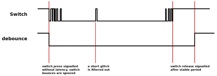
The relevant changes are on lines 7 and 8 on the source code snippet below: the vertical counters are incremented only on switch release, but forced to zero on switch press. If the debounced state was not already set to “pressed”, the state is toggled when the count is zero (and, as said, the count is forced zero in this case).
1 2 3 4 5 6 7 8 9 10 11 12 |
unsigned char debounce(unsigned char sample)
{
    static unsigned char state, cnt0, cnt1;
    unsigned char delta;

    delta = sample ^ state;
    cnt1 = (cnt1 ^ cnt0) & (delta & sample);
    cnt0 = ~cnt0 & (delta & sample);
    state ^= (delta & ~(cnt0 | cnt1));

    return state;
} |
In case a switch is connected so that it switches to the VCC voltage rail, instead of to ground, this same basic algorithm can be used, with the change that on entry, parameter sample must be inverted, and the return value must be the inverted value of variable state.
Closing remarks
The debounce functions presented here should be called on a regular interval, such as from a timer interrupt. The suggested interval is between 5 ms and 10 ms, so that a switch will be signalled as pressed or released between 20 ms to 40 ms after it has stabilized. The timings are not critical, but switch latencies above 50 ms are often already noticeable.
Vertical counters allow for an elegant, compact and efficient debouncing algorithm which can debounce multiple inputs concurrently. Furthermore, this method can achieve very low latency (the maximum latency is the interval with which the switch is polled). The low-latency modification works on either one of the two state transitions of a switch (but not on both).
