Power-outputs for the programmable audio controllers/players
The H0420 programmable MP3 controller/player has 16 general purpose digital I/O pins. The Starling audio controller model H0440 has 8 general purpose digital I/O pins. These pins can be programmed (of course) to be either input or output, and they adhere to TTL signal levels. When configured as outputs, each pin can furnish up to 20mA, sufficient to directly drive a LED or an opto-coupler.
The I/O pins of the H0420 are protected against short-circuit with an internal 220Ω resistor. When a yellow LED is branched at an output, the current flowing through that LED will be approximately 12mA (the forward voltage of the yellow LED is approximately 2.2V, so the voltage across the internal resistor is the high level of a TTL gate minus 2.2V, or rougly 2.6V; this results in a current through the resistor of 12mA). Other colours of LEDs have different forward voltages and the current flowing through these LEDs varies accordingly.
For the H0440, the internal resistor is 120Ω, but the I/O voltage is 3.3V by default. A yellow LED will draw 9mA in this default configuration. The I/O voltage can be programmed, on the H0440.
When the controllers must drive something that has a little higher power requirements, either current or tension, you have several options ranging from analog switches, to (solid-state) relays. A simple, effective and cheap way, though, is with a circuit consisting of a single power transistor and a resistor.


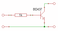
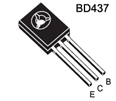
The above schematic shows the simplicity of the circuit. The power transistor is in a typical "common-emitter" configuration. Although the schematic shows a BD437, many power transistors are suitable (e.g. 2N5190). The 1k resistor limits the current through the base of the transistor. If you use a different transistor, you may need to adjust the 1k resistor.
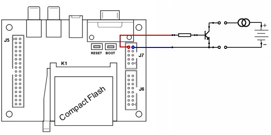
The left side of the schematic connects to any of the I/O pins of the H0420/H0440 controller. The right side can switch a tension of up to 20V and 4A (but the transistor needs a cooling radiator for such high currents). This circuit is almost too simple to build a PCB for, and therefore it has often been constructed right on top of a crimp connector. In the figure below, the circuit is connected on the H0420 to I/O pin 15 and its associated ground pin. These two pins are at connector J7 of the H0420 MP3 controller.

Further reading & references
- H0420 Programmable MP3 Player
- The main page for the MP3 player that this article applies to. Many of the application notes use the digital I/O lines to drive LEDs or other electronics.
- Starling model H0440, with dual decoder
- A description of the Starling audio player/controller, model H0440, which (like the H0420) is programmable and has general purpose I/O pins.

