

A remote-controlled audio player
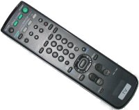
Although our programmable audio players do not have an infrared receiver module pre-fitted, it takes only a cheap receiver, a few passive components and a special script to be able to control the audio player with a common infrared remote control (such as the ones used for television and VCR).
A typical infrared receiver module has three pins: ground, power and signal. I used the HIM702 receiver (HERO Electronics), but the popular TSOP 113x and 173x series (VISHAY) work equally well. When using the H0420 MP3 player/controller, you need to add a pull-up resistor on the "signal" line, because the I/O pins of the H0420 have only a weak pull-up when configured as input (the Starling audio player/controllers have 10k pull-up resistors on the I/O pins). In general, it is advised to add a filter on the power line. A typical circuit is below.
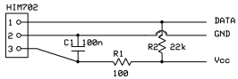
Connecting the HIM702 IR receiver
If you have a long cable between the infrared receiver and the device that it is linked to, you may need a larger capacitor than the 100 nF in the schematic, in order to reduce the electronic noise. Some infrared receivers have a power regulator internally, so that the filter (R1 and C1 in the above schematic) can be removed. A receiver like the PNA4602M also has an internal pull-up resistor, so that no external components are needed at all.
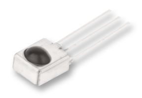 HIM702 IR receiver |
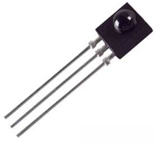 PNA4602M IR receiver |
The needed ground and power (Vcc) lines are available on the connector J6 of model H0420 (pins 1 and 2), and on the connector P9 of model H0440 (pins 11 and 12). The "data" line can be connected to any of the IO-pins.
Once the IR-receiver is connected, you must write a script to take advantage of
it. First, you must configure the pin. If you connected the signal line to IO-pin 10,
you would set this pin to "Sample" (timed input), as in the code snippet
below. The time-out value depends on the protocol that the remote control uses
to send commands; for decoding RC5 codes, 25 ms is a good
time-out.
#include <rational>

main()
    {
    configiopin 10, Sample, 25
    }

@sample(const Fixed:stamps[], numsamples)
    {
    /* here, you need to add code that checks the time stamps in the
     * "stamps" parameter to determine which buttons is pressed on
     * the remote control
     */
    }
What this initialization tells you is that pin 10 must be sampled as soon as it
state changes, for a duration of 25 milliseconds. After this period times out,
the device invokes the public function @sample() with the time stamps
of the state changes. These time stamps are relative to the time that sampling
started.
The function @sample() receives the time stamps in milliseconds, but
the values are fractional. Internally, the device measures the time stamps in
microseconds. This is also why the above code snippet has an #include
for the file "rational", to enable rational number support. The
pawn system as implemented in the audio players supports fixed point arithmetic
with three decimal digits.
Interpreting the sample data
The device starts sampling data as soon as the state of the input pin changes,
either from high to low, or from low to high. What it passes to the @sample()
function are only the time stamps of these changes, not whether they go up or down.
However, you only need to know the direction of the first state change; since each
time stamp signals a toggle of the pin level, you can derive the pin level at any
moment in time from the initial state. For the audio player, the initial state is defined
as "high", so the first state change that is recorded is a transition from high-level
to low-level. This occurs at time stamp zero, because this change also starts the
sampling and all subsequent time stamps are relative to the start.
As it is always present, the zero time stamp that starts the sampling is not
in the array passed to @sample(). That is, when the first element in
the array passed into @sample() is 1.000, the signal at the input pin
(pin 10 in our examples) is low between 0.000 ms and 1.000 ms (relative to the start
of the sampling); at 1.000 ms, the signal toggled high.
Most infrared receiver either pull the signal pin high when they are idle or require
that you add an external pull-up resistor (such as the HIM702 that I am using).
But suppose that we have a receiver that is low when idle and pulses high when it
receives a command. In this situation, the first element in the array passed to
@sample() will be zero: the audio player starts sampling at the
initial transition from low to high level, but as it defines the start as being
high, it inserts a fictitious transition from high to low before the other transitions.
That is, the first (implied) transition is from high-to-low and the true transition
from low to high happens at 0.000 ms after the start of the sample. The "low period"
then takes zero time.
In practice, when the first element in the array is 0.000, the sampling burst was fired by an initial transition from low to high. Otherwise, it was a transition from high to low that fired the sampling burst.
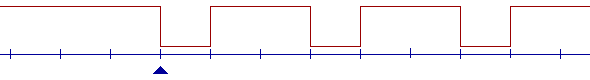
Values in the stamps parameter: 1.0, 3.0, 4.0, 6.0, 7.0
|
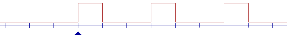
Values in the stamps parameter: 0.0, 1.0, 3.0, 4.0, 6.0, 7.0
|
The above graphs assume that each mark at the time line represents a millisecond.
The sampling starts at the position of the triangle (meaning that the signal has
been stable up to the time marked with the triangle). As the time stamps passed the
the @sample() function are relative to the start of the sampling,
the triangle also marks the "0.0" time. The two graphs are the reciprocal
of each other. The time stamp values for both signal are the same, but in the
second signal, there is an extra "0.0" time stamp because the initial
flank goes up (from low to high).
RC5 decoding
As may be expected, appliance manufacturers have attempted to standardize the
protocols used by remote controls and the remote-controlled apparatus. No single
standard has surfaced yet, though. Several standards exists side-by-side, and remote
controls that implement a custom protocol exist too. The @sample()
function lacks pre-programmed support for any specific protocol, but through
analysis of the raw time stamps (of the high-to-low and low-to-high transitions)
any protocol can in principle be supported.
For purpose of illustration, I will give an example for decoding the RC5 protocol. This protocol, designed by Philips, contains 14 bits in each burst, where a burst takes 24.889 ms. The definition of the 14 bits is below.
| 2 start bits | These should be 1's. |
| 1 toggle | This bit toggles from 1 to 0 (and vice versa) for every individual button press; it does not toggle when a code is repeated due to a button being kept pressed. |
| 5 group bits | The "group bits" identify the apparatus (the "address"). |
| 6 command bits | The bits that hold the command. Many commands are predefined. |
Every "bit" takes 1.778 ms in the protocol. A 1 (one) bit is defined as there being a transition from low to high halfway the period for the bit. A 0 (zero) bit has a transition from high to low. This is called "bi-phase" modulation or "Manchester coding". See the References section at the bottom of this paper for a link to a page explaining this in some detail. An advantage of bi-phase modulation is that the transition halfway the period for a bit can also serve to synchronize the timing circuit of the decoder to the signal.
A complete command (or 14 bits) is repeated every 114 ms, as long as the button for that command is held down. The toggle bit has the same value for all of these repeated commands; only when a button is released an pressed again, will the toggle bit change from 1 to 0 or vice versa. Software can use the toggle bit to check whether there was a button release between two commands.
To see whether a bit is up or down, the @sample() function that is
presented below looks at the level of the signal shortly after the time slot for
the respective bit starts. That is, when testing the first bit, the @sample()
function must test the status of the signal time-stamp 0.0 (as explained earlier,
the first sample starts at time stamp 0.0 by definition) and before the signal
toggles halfway the time slot. Since the slot's duration is 1.778 ms, the signal
for the first bit must be checked between 0.0 ms and 0.889 ms. A good choice, then,
is halfway these limits: at 0.445 ms, or 1.778 / 4 ms. This is what the function
does.
For the next bit, the function adds 1.778 ms to its time criterion (for the next time slot) and checks the signal state at 1.778 + 0.445 ms. And so on for the remaining 12 bits.
const Group = 0

@sample(const Fixed:stamps[], numsamples)
    {
    new code = 0                /* the result will be stored here */
    new Fixed:stamp = 1.778 / 4 /* check bits at 0.445 ms from the slot */
    new curbit = 1              /* we start with a "1" bit */
    new sample = 0              /* index in the "stamps" array */

    for (new i = 0; i < 14; i++)
        {
        while (sample < numsamples && stamps[sample] <= stamp)
            {
            curbit ^= 1
            sample++
            }
        code = (code << 1) | curbit
        stamp += 1.778          /* move to next slot */
        }

    /* we accept only codes that begin with 2 start bits, and that
     * belong to the correct group
     */
    if ((code & ~0x83f) == (0x3000 | (Group << 6)))
        rc5code code
    }
Instead of just "getting" a signal status on a time-line, the @sample()
function must calculate the status that the signal will have using the time stamps
of the signal transitions. The function keeps the current bit in the local variable
curbit and toggles it for each transition that occurs before
the sample time.
Once all bits are decoded, the function checks for the double "1" that indicates
the start of a sequence and it also checks whether the address in the code matches the
one for this device. In this example script, Group is a constant that
is set to zero (the address for the first television set), so that you would be
able to operate the audio player with a television remote control. You could also read
the address for a audio player from a configuration file on the CompactFlash card and
use a single remote control to control several audio players.
If the code is valid and the address matches, the @sample() function calls another function,
rc5code(), which must handle the command in the code. Function
rc5code() extracts the toggle bit, and uses it to tell whether a
code was repeated or not. The channel up or down codes will ignore repeat codes,
to avoid flipping through all tracks with a rate of 7 tracks per second. For
the volume up and down codes, you will to just keep increasing or decreasing
the volume as long as the button is held on the remote control. In that case, you
make no difference between repeat codes and normal "press" codes.
#include rc5codes

rc5code(code)
    {
    /* extract the current toggle and determine whether this is
     * a repeated command
     */
    static CurrentToggle = -1

    new togglebit = (code & 0x800)
    new repeat = (togglebit == CurrentToggle)
    CurrentToggle = togglebit

    /* handle on the command */
    switch (code & 0x3f)
        {
        case ChannelUp:   nexttrack repeat  /* routine not shown */
        case ChannelDown: prevtrack repeat  /* routine not shown */
        case VolumeUp:    volumeup          /* routine not shown */
        case VolumeDown:  volumedown        /* routine not shown */
        }
    }
The include file "rc5codes.inc" (not shown, but available in de
download section below) contains a list of predefined
codes for RC5 remote controls. There exist even more codes; the References
section at the end of this paper contains a link to a page with a comprehensive list.
From these predefined codes, the example script function presented here only
catches channel up/down and volume up/down. Other commands (e.g. direct track
selection through numbers) can be added with ease.
For longer time series, we might need to consider deviations and incremental
rounding errors. The duration of a time slot is actually 1.7777857 ms instead of
1.778 ms; the 0.2 µs difference might accumulate to a fairly large error over
a long series of bits. In addition, both the timers of the remote control and of
the H0420/H0440 audio players might be slightly off specification. As mentioned
earlier in this paper, the bi-phase modulation enables software to synchronize the
clocks in case of a deviation. A transition must appear halfway the slot,
so you can predict where the transition should be and adjust your internal timer
by the difference with the transition moment that you measured. Since the RC5
code is relatively short, the @sample() function presented here
makes no attempt to synchronize its calculated time slot boundaries with the time
stamp values.
Downloads
To get you started, below is an archive file with a complete script and a few support files. You can run this script as is, or modify for your purposes.
- A script file that implements a simple RC5 decoder, that you can put on a CompactFlash card and run.
The script assumes that there are eight tracks on the CompactFlash card, called "track1.mp3" to "track8.mp3". There are several files in the archive; the main file (the file to compile) is "remotectrl.p". The file "rc5decode.inc" contains the RC5 decoder and "rc5codes.inc" has a list of predefined codes.
The script in the archive assumes that the data line is on I/O pin 11, which is on connector J5. I have chosen this line so that one can branch an LCD to connector J6, e.g. for testing purposes. (The script in the archive does not use an LCD, by the way.) Of course, the data line is trivially changed to any other I/O pin, if so desired.
End notes
Although RC5 is popular, there are many protocols for remote control in use today. With procedures similar to the implementation in this paper, the H0420 and H0440 audio players can decode most of them. If fact, I started with decoding an old (but tiny and convenient) remote control with an undocumented protocol; I later adapted the routines to RC5 code for the publication of this paper (you are unlikely to have a remote control that uses the same undocumented protocol as the one I was initially using).
All code snippets on this page are in the pawn embedded scripting language, which is the scripting language implemented in our programmable audio players. The pawn development tools are freely available.
A lot of schematics for connecting an infrared receiver to a PC float on the Internet; see for example the LIRC page. Most of these circuits branch to the RS232 port, which may lead to the misconception that these IR receivers are compatible with the RS232 protocol. They are not. Most IR receiver circuits that were built to connect to the RS232 use the RS232 in a non-conforming way. If you branch such a device to the RS232 port of the H0420 or H0440, it is unlikely that these circuits will work. Only devices that adhere to the RS232 standard (and that use either software handshaking or no handshaking at all) may be connected to the H0420/H0440.
In fact, the common schematics for IR receivers on the the RS232 use the RS232 port primarily because its data pins can deliver sufficient current to abuse them as a power supply. The output of the IR receiver is often connected to the CD (Carrier Detect) line, which is not designed for data transmission (no FIFO, no latch register or other hardware support). This explains, in turn, why the standard serial port driver is unsuitable for interfacing with these circuits.
There are hardware problems too: the output levels are 0V and 5V for low level and high level respectively, but the RS232 norm wants -12V..-3V for low level and +3..+12V for high level (according to the LIRC page, the majority of the RS232 ports on desktop PCs accept the a range of -12V..0V for low level, which is why the schematic works at all). All in all, these circuits look more like a hack than a design.
On the other hand, as this paper shows, a typical circuit that is compatible with our audio players is even simpler than those for the RS232 (especially when using the PNA4602M, which requires no external components at all), and in addition it leaves the RS232 port(s) free for other uses.
Further reading & references
- Programmable MP3-player for kiosk applications
- A programmable MP3 player/controller, with digital I/O ports that can be sampled at fairly high speed.
- Starling audio player, model H0440
- A programmable audio player/controller, with fast digital I/O pins.
- Connecting a bar-code wand to the MP3 controller/player
- An article on another use for the "pin sampling" feature of the H0420 MP3 controller. In this article, the infrared receiver chip is replaced by a low-cost (undecoded) bar-code wand. A wand is a pen-shaped bar-code reader.
- VISHAY - Infrared Receiver Modules
- An overview of the IR receivers produced by VISHAY, including data sheets. Although the TSOP 1738 is marked as "not for new designs" by VISHAY, it remains a popular device.
- Farnell in one
- Data sheets for alternative IR receiver modules, such as the HIM702 that I used for this paper, are most conveniently found through "Farnell in one".
- Philips RC-5 Protocol
- A brief description of the RC5 protocol, plus tables of common commands and group IDs.
- RC5 codes
- A plain list with many known predefined commands for the RC5 code, as well as for the extended RC5 code.
- Digital transmission - line coding
- A description of various signal encodings. In relation to this paper, the description of bi-phase modulation (Manchester coding) is relevant. Two Wikipedia articles that describe the encoding are "Biphase Mark Code" and "Manchester code".
- The LIRC page
- The web site for LIRC: infrared remote controller support for Linux applications.
