

The STA013 and STA015 MP3 decoders
The "STA013" and "STA015" integrated circuits by STMicroelectronics are flexible MP3 decoders with good performance. The STA015 is almost fully backwards compatible with the STA013, so this article will focus on the STA013 and mention differences with the STA015 where applicable. (Note that the STA015 is no longer generally available.)
The goal of this article is to collect information that is gained from working with the chip, and that is not readily available in the datasheet or the application notes for the STA013 and STA015 ICs. As such, this article augments the datasheet and the application notes, but it does not replace them.
A brief technical introduction
The STA013 uses an I2C interface for "control" and an SPI-compatible interface for data. The digital PCM data that it provides on its outputs can be in one of various standard formats (among which I2S). Typically, you can connect the STA013 directly to a Digital-Analogue Converter (DAC), because the STA013 also generates the (oversampling) clock for the DAC.
To feed the compressed data into the decoder, the STA013 supports a serial data interface that is compatible with the SPI bus ("Serial Peripheral Interface", developed by Motorola) and that allows a bit stream of up to 20 MHz. Control commands for the decoder go over the I2C bus, at a maximum frequency of 400 kHz. The decoder is, in fact, a DSP (digital signal processor) with a fairly large number of internal registers, many of which are undocumented.
To get the STA013 started, you will first need to upload a "configuration file" with over 2000 assignments of values to registers. STMicroelectronics provides this configuration file as an ASCII file with a register number and a value per line. Some references in the STMicroelectronics documentation call this file the patch file, which suggests that this configuration file fixes minor issues that have been found after the STA013 went into production. However, without this patch, the STA013 will not run. After loading the file, you need to configure a few more registers depending on the crystal (clock frequency) and the desired input and output interfaces. The STA015 does not need a "patch" file to be uploaded, but it needs the same crystal/clock configuration as the STA013.
The "data feed" to the STA013 goes via a serial protocol that is compatible
with SPI. In this data protocol, the microcontroller must first select the STA013
chip by toggling the "BIT_EN" line high; then it clocks in the
eight bits of data in each byte, starting with the most significant bit. The
BIT_EN can stay high during the transfer of all bits/bytes; there
is no need to pulse it between two bytes. Normally, SPI is also defined for
16-bit data transfers, but the STA013 requires 8-bit data transfers.
As the SPI protocol has no method to acknowledge accepted bytes (unlike I2C),
the slave device must either accept anything that the master device
pushes into it, or have some other means to signal the master when to stop
sending. The STA013 handles synchronization through the DATA_REQ
line (a separate pin on the IC). The master device should check the status of
this line after writing each full byte. The datasheet for the STA015 documents
that it drops the DATA_REQ low when its internal buffer has room
for at most four additional bytes.
Audio data buffers
The STA013 processes the MP3 audio data per frame. A frame is an independent block containing a fixed number of compressed samples that follow a 4-byte header (see also the next section of this paper). The format of the MP3 files were designed this way to enable streaming of music files (e.g. over the Internet). You can pick up any MPEG audio stream mid-way, starting at the first frame header that you detect. There is never a need to seek from the start of the file to the desired position. The frame header allows the STA013 to skip over any non-audio data, such as an ID3v2 tag. A sequence of 11 bits that are set (1) indicates the start of a frame.
Due to the "bit reservoir" that most layer 3 streams use, frames are, in practice, not independent of each other. When an MP3 decoder must pick up a stream halfway, it will mostly produce silence or an arbitrary noise for the first few frames.
In a lesser sense, the Modified Discrete Cosine Transform (MDCT) that MP3 encoding uses also makes frames interdependent. MDCT is an overlapping encoding where the samples in the first half of a frame combine with those that are actually part of the predecessing frame. When starting in the middle of an audio clip, the first frame is only partially decoded.
Our experiments show that the STA013 keeps its DATA_REQ high until
it has loaded a complete frame. The size of a frame, in bytes, depends on a number
of parameters, notably the bitrate and the sampling frequency; it grows to over
1 KiB of 320 kb/s 44.1 kHz tracks. The STA013 needs to have that amount of
memory internally. It might have a larger buffer size, so that it can accept
the next frame while playing an active frame.
We attached theDATA_REQline to an interrupt and pushed a high-precision time stamp in a queue at every interrupt. Our statements about the size of the internal buffer of the STA013 are based on observations of the interrupt timestamps when sending tracks with different sampling frequencies and bitrates to the STA013. With tracks at 44.1 kHz, we observed pulses of theDATA_REQline at intervals of 26.1 ms, regardless of the bitrate of the track. When sending a track sampled at 48 kHz, theDATA_REQpulsed at 24 ms. These measured values match the durations of the MP3 frames at 44.1 kHz and 48 kHz respectively.
An e-mail exchange with a STMicroelectronics engineer confirmed our findings about the buffer size. He described the design as a dual-buffer: a back-buffer that holds a complete frame (which the decoder works on) and a front-buffer for prefetching the bytes for the next frame.
Additionally, the STA013 has an internal MP3 parser that skips any non-MP3 data,
such as ID3 tags. You can therefore feed an MP3 file into the decoder without
needing to parse it yourself. This parser runs parallel with the reception of
input data: when a large ID3 tag is present in a file, it is immediately rejected
and the DATA_REQ stays high until the STA013 has received a full
valid frame. If you would feed a non-MP3 file into the STA013, the DATA_REQ
will never go low at all, regardless of the size of the file that you push into
the chip.
The STA013 can give you the header of the frame that it has just started decoding. Or rather, it gives you three of the four bytes of the header (since the first byte of an MP3 frame header is all 1s, it never contains relevant information). The bitrate for the active block is in this header information. In variable bitrate files, this field may change from one frame to the next. Another register in the STA013 gives you the average bitrate. This register will allow you to estimate the duration of the music sequence —it remains, however, and estimate.
Handling the audio frame-by-frame makes sense for handling variable bitrate files, but it also opens possibilities for or making sound loops. To make a loop, you basically clock in the first block of an audio file again after having completed the last block. The STA013 has no knowledge of files, only frames and there is no need to "stop" the MP3 playback in the STA013 at the end of one file and to restart it at the next. Making seamless loops, without plops or gaps, is not quite so easy, though —see the separate article "Gapless looping MP3 tracks".
Stopping a track (clearing buffers)
To abort a playing track, you can simply send a command over the I2C bus to set the "play" register to zero. However, this does not reset the internal buffers of the STA013. If you resume the track at the same position, there is no problem. However, if you wished to stop the track and play a different track at some later time, you will notice that the STA013 first pushes out some samples of the stopped track. Evidently, these samples were still in a buffer.
The only way that we have found to clear this buffer is to reset the STA013; sending a "soft reset" command is sufficient. The drawback is that, after the reset, you need to send the configuration file again. Sending those 2007 register settings over I2C takes some time. In our code, with I2C running at 400 kHz, the complete reset procedure took roughly 220 ms. This only applies to the STA013, as the STA015 does not have a patch file.
Tone controls
The description of the bass and treble controls is very brief in the datasheets of the STA013 and STA015. There are five settings in total: bass filtre frequency, bass gain, treble filtre frequency, treble gain and a general tone control attentuation. To start with the latter: when you use a positive gain for bass or treble, the volume must be attenuated by at least the same amount, because the gain cannot raise above unity gain. For example: if the bass gain is 6 dB and the treble gain is 12 dB, the tone control attenuation should be 12 dB (the highest of the two). If you set the tone control attenuation to 6 dB, the treble filter will not reach the 12 dB level, as it clips to unity gain.
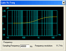
The bass and treble controls each create a double-knee curve. The picture shows a curve with the treble frequency set at 1.5 kHz and the gain at 18 dB; the bass controls are not used (zero-gain).
For filters, the cut-off frequency is usually defined as the frequency where the gain is +3dB or -3dB from the adjoining horizontal section of the curve. A double-knee curve has two cut-off frequencies. From inspection and experiments, we have found that, at a gain of +18 dB (or -18 dB), the cut-off frequencies of the filter are at approximately:
\[ \eqalign{ f_{c1} &= 0.25 \cdot f \cr f_{c2} &= 1.75 \cdot f } \]where f is the frequency passed to the STA013 for its bass or treble settings. As is apparent from these figures, the frequency that you pass to the STA013 lies exactly in the middle of the two cut-off frequencies. An alternative (one that I would prefer) would be to pass in the frequency where the gain is half that of the total gain. This frequency is at 0.66 · f.
The roll-off rate (the slope of the curve) is approximately:
\[ S = 4.6 dB/octave \]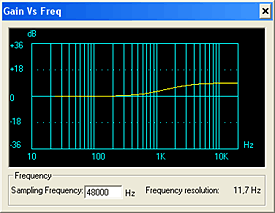
When the gain is lower then ±18 dB, the roll-off rate decreases proportionally. I prefer to consider the cut-off frequencies as being independent of the gain, even though this is not quite accurate: since the cut-off frequency is defined as the point where the gain is ±3 dB from the horizontal section, it depends on the roll-off rate. The picture at the right has the same settings as the previous picture, except that the treble gain is at +9 dB.
Internal clocks, PLL & clock synchronization
The datasheet for the STA013 contains several tables for the settings of the clock multiplication and division registers, and ST Microelectronics also provides a utility ("ConfigPLL") to calculate the values. Nevertheless, the issue is somewhat confusing, partly due to the many registers that are involved and a few inaccuracies in the datasheet.
The clocks are ultimatedly derived from a crystal. The STA013 supports several
crystal frequencies; in its datasheet, ST Microelectronics calls the crystal
frequency XTI. This frequency goes through a multiplier
into a Phase-Locked Loop (PLL) with a divider. The multiplier is called the
M register and its value is also referred to as
MF (probably standing for "Multiplication Factor");
the divider is the N register and its value is
called IDF (our best guess: "Integer Division Factor").
Figure 7 on page 8 of the most recent datasheet (February 2004) has theMandNregisters swapped. In the description of theMandNregisters, the datasheet states that the values of these registers "are completely controlled, on STA013, by DSP software", suggesting that you should leave these values alone. This is not true, these registers need to be set (by you), and in fact, the DSP software does not change these registers.
The internal frequency, which is the basis for all other clocks, is called
VCO. From the figure 7 in the datasheet and a few experiments, we
believe that the relation between VCO and the crystal frequency is:
In all tables, as well as in the output of the ConfigPLL utility, register N
is always zero, so the above equation can, in practice, be simplified to:
The PLLFRAC value is a register pair,
consisting of two 8-bit registers. This pair is at the undocumented addresses
0x08:0x09, but the STA013 copies it from either of two (documented)
register pairs: 0x51:0x52 for tracks with a sampling rate of 44.1 kHz
(and other multiples of 11.025 kHz), and 0x64:0x65 for tracks with
a sampling rate of 48 kHz (and other multiples of 8 kHz).
Changing the PLLFRAC fields allows for fine-tuning the clock frequencies, which
is important in the case of life-streaming audio (the receiver must synchronize
the rate at which it "consumes" audio to the rate that the transmitter produces
it). However, the STA013 reads these registers only when encountering a frame
with a different sampling frequency than the previous one, and after a reset (a
"soft" reset is sufficient). Therefore, the VCO frequency cannot be adjusted
seamlessly while playing audio.
The STA013 drives the DAC and provides the clock for the DAC. This clock is called
OCLK; it is the VCO
clock divided by an integer value:
There are two registers for the MFSDF value: one
for playing tracks with a 44.1 kHz sampling rate and one for tracks with a
different sampling rate. The datasheet has the details.
Frame size and frame duration
There is a wide-spread misconception that a frame of an MP3 file is defined at 26 ms. Even if this may be valid for most MP3 files, it is inaccurate. Typically, an MP3 file stands for MPEG 1, layer 3, at 44100 Hz. For these files, each frame contains 1152 samples, and their duration is indeed approximately (but not exactly) 26 ms. The sampling frequency configurable, however, and MP3 audio files sampled at other rates than the ubiquitous 44.1 kHz certainly exist. Depending on the MPEG version and the layer, the number of samples per frame may also differ from 1152. The article "MPEG Audio Frame Header" (see references) has all the details.
To calculate the size in bytes of a frame, the criterion are the bitrate and the number of frames per second. The bitrate gives the number of bits per second, and this number includes the headers of the frames. Divide this number by 8 to get the number of bytes per second; then divide it again by the number of frames per second to get the size of a frame in bytes. The number of frames per second is, of course, the inverse of the frame duration. There are three caveats in the calculation of the frame length that you must take into account:
- The number of bytes per frame may come out of the calculation as a fractional value. In that case, the MP3 file has frames with a byte size that is the computed value rounded down and frames with the computed value rounded up. The header of a frame indicates the occasional extra byte with the "padding bit".
- The frame sizes are rounded up to a "slot size". The size of a slot is just one byte for layers 2 and 3, but it is four bytes for layer 1.
- It has been reported that, in practice, the frame size is sometimes a little "off spec". Some encoders appear to "pad" frames with a few extra bytes on specific circumstances. An MP3 decoder must be robust against this and it can check for the "sync marker" (eleven consecutive 1 bits starting at a byte boundary) to find the real start of a next frame.
For the common case of MPEG 1 layer 3, the duration of a frame is: \[ 1152 \over {sample\ rate} \] and the size of each frame in bytes is: \[ {1152 \times bitrate} \over {8 \times sample\ rate} \]
Note that the bitrate value is the number of bits of compressed data that must be pushed into a decoder (and that the bitrate value includes the size of the frame headers). The MP3 compression algorithm is a combination of domain transform and quantization, plus a statistical lossless compression scheme called "Huffman compression". In the domain transform and quantization phase, you may calculate deterministically what your compression ratio is, but you have no idea to how many bytes this will be reduced in the Huffman coding step. If you quantize too coarsely, quality suffers; if you quantize too finely, the frame size will exceed the set bitrate. However, you will only know the size of the frame until after the Huffman coding phase has finished. As you can imagine, an encoder uses an iterative procedure to find the optimal settings for each frame.
References
- STMicroelectronics STA013
- Information on the STA013 from the manufacturer, including a link to the datasheet.
- Programmable MP3-player for kiosk applications
- Our product: a programmable MP3 player/controller, which uses the STA013.
- MPEG Audio Frame Header by Konrad Windszus
- This article contains detailed and up-to-date information on the MPEG audio file format, and especially the frame headers.
